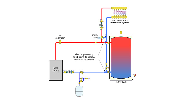
Schematic Chilled Water Buffer Tank Piping Diagram

Heatspring Magazine 2 Pipe Versus 4 Pipe Buffer Tank Configurations

Impovements To Ergomax Buffer Tanks
Alternate Methods To Pipe A Buffer Tank 2014 10 22 Plumbing And Mechanical
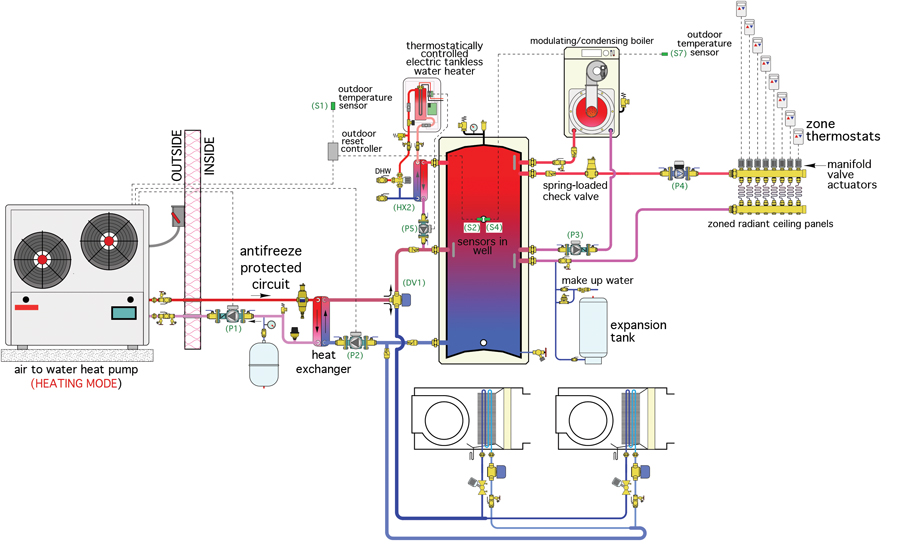
Heat Pump Plus Hpac Magazine
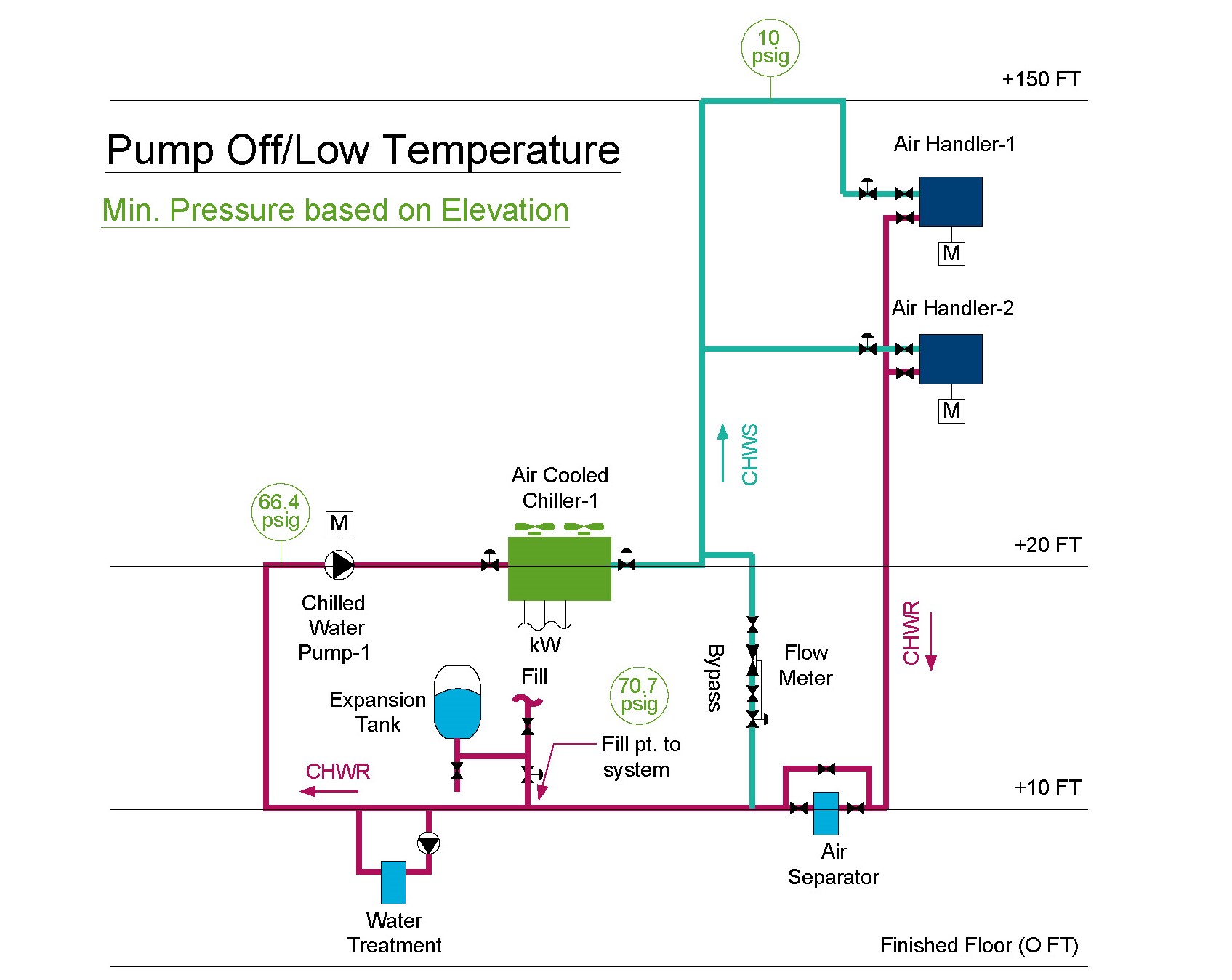
Expansion Tank Design Guide How To Size And Select An Expansion Tank For A Chilled Water System

Hot Water Storage Tank Piping Diagram Water Storage Tanks Reverse Osmosis Water Water Tank

System flow below chiller min flow 250 gpm variable primary flow at 25 system load two way valves control capacity by varying flow of water in coils per chiller system load 50 tons 176kw 50tons 176 kw primary bypass flow 250 gpm 95 l s 150 gpm 9 5 l s delta t 12 of 6 7 oc 100 gpm 44 ºf 6 3 l s 6 7 ºc 56 ºf 13 3 ºc 150.
Schematic chilled water buffer tank piping diagram.

Ecopower Principles

Spec Check Issue 1 Buffer Tanks Masterflow Solutions

Wheeler Tank Manufacturing Inc
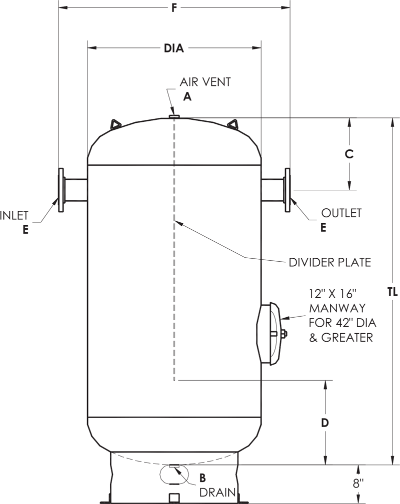
Asme Storage Tanks Elbi Of America Houston Tx
Source : pinterest.com
